Systems
Committed to Excellence
Standardized hydraulic press systems designed and built to deliver exceptional performance.
Interlaken Technology designs and builds several standardized lines of hydraulic presses and high pressure testing systems. For part forming ITC features tube hydroforming and elevated temperature systems. For material testing ITC offers five servo press systems, bend, dent and draw bead applications, leak and burst testers, and autofrettage.
Hydroforming
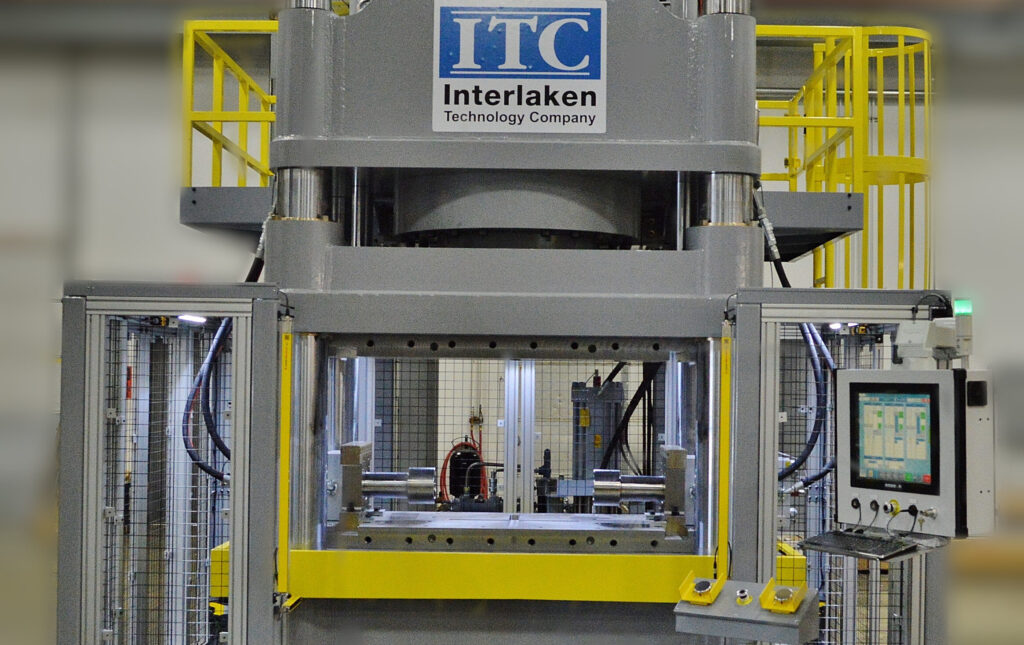
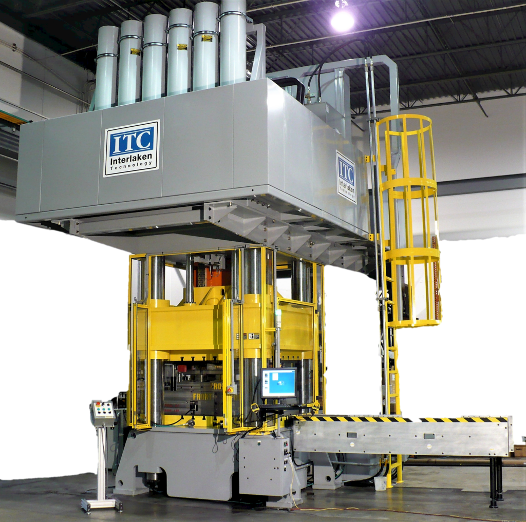
Interlaken Technology has been designing and manufacturing exclusive hydroforming systems for over 20 years. From a 50 Ton hydroforming press for university research to a 2000 Ton production press for manufacturing, ITC’s hydroforming systems fill a variety of needs.
The ITC press optimizes tube forming. Tube hydroforming reduces weight, reduces component part count, lowers assembly costs, and increases strength and stability. The system features mode switching from stroke to pressure feedback for control, and complete independent control of clamp, feeds, and pressure. This results in a highly repeatable process to maintain tight tolerances.
Customers may choose from one of our standard hydroforming systems or ITC can build an optimized solution for your specific application. ITC presses provide closed loop control of forces, motions and pressures to produce high quality parts. Our exclusive, easy-to-use software allows users to develop complex force, motion and pressure profiles for consistent tube forming applications.
The system is comprised of five sub-systems:
- A single or multi-acting, servo-controlled hydraulic press with mode switching during the process.
- Servo-controlled Hydroforming Feed Actuators that are fully integrated.
- A Servo-controlled Pressure Intensifier with pressure control valves. A variety of pressure and flow options are available.
- Interlaken designed tooling with changeable die inserts for differing cavity shapes that can be run with or without end feed.
- A B&R PC that controls the PLC I/O and HMI.
Learn more:
- Bellows
- Tube
Bellows Hydroforming
Metal Bellows are thin wall cylinders with convolute structures perpendicular to the cylinder’s axis. The convolutes enable the component to be highly flexible during axial, lateral, and angular deformation. Hydroforming can provide faster and more reliable forming of the convolutes, meaning less scrap and higher repeatability of critical geometry.
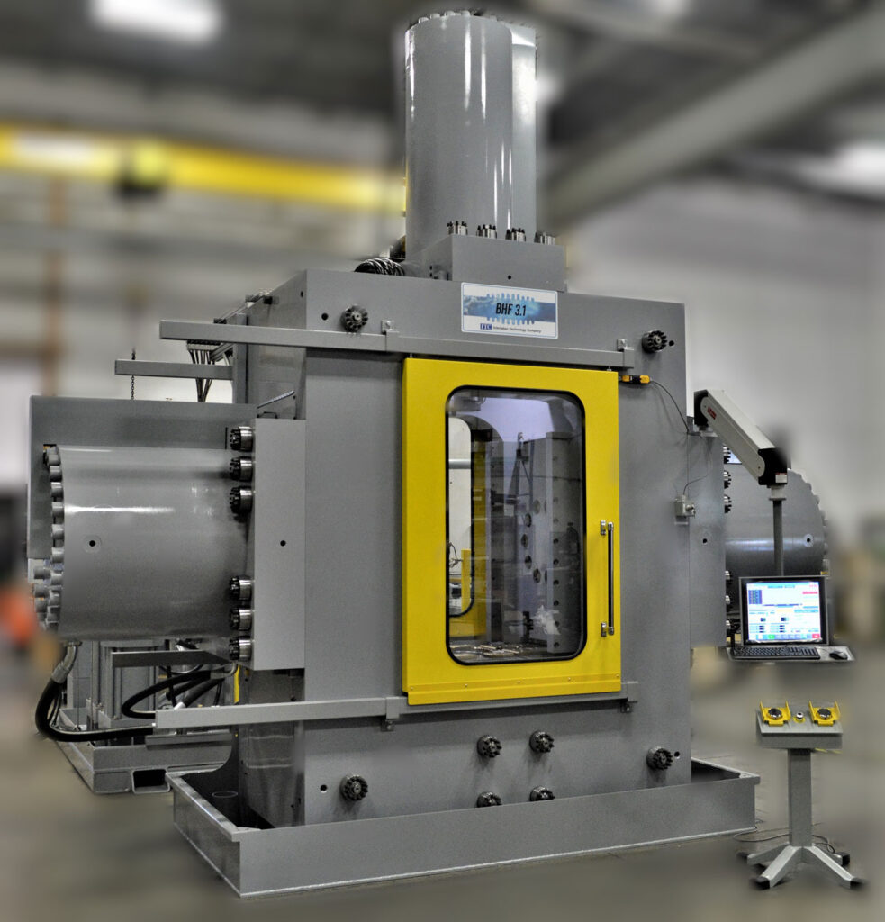
Large Bellows
ITC designs the system based on the size and number of convolutes in your part. ITC defines a large bellows system as one that produces parts with a convolute diameter of 4″ to 16″. The smaller the diameter the higher the pressure needed to form the part. ITC tailors the pressure accordingly, using one to three intensifiers with pressure from 5000 to 30,000 psi.
Small Bellows
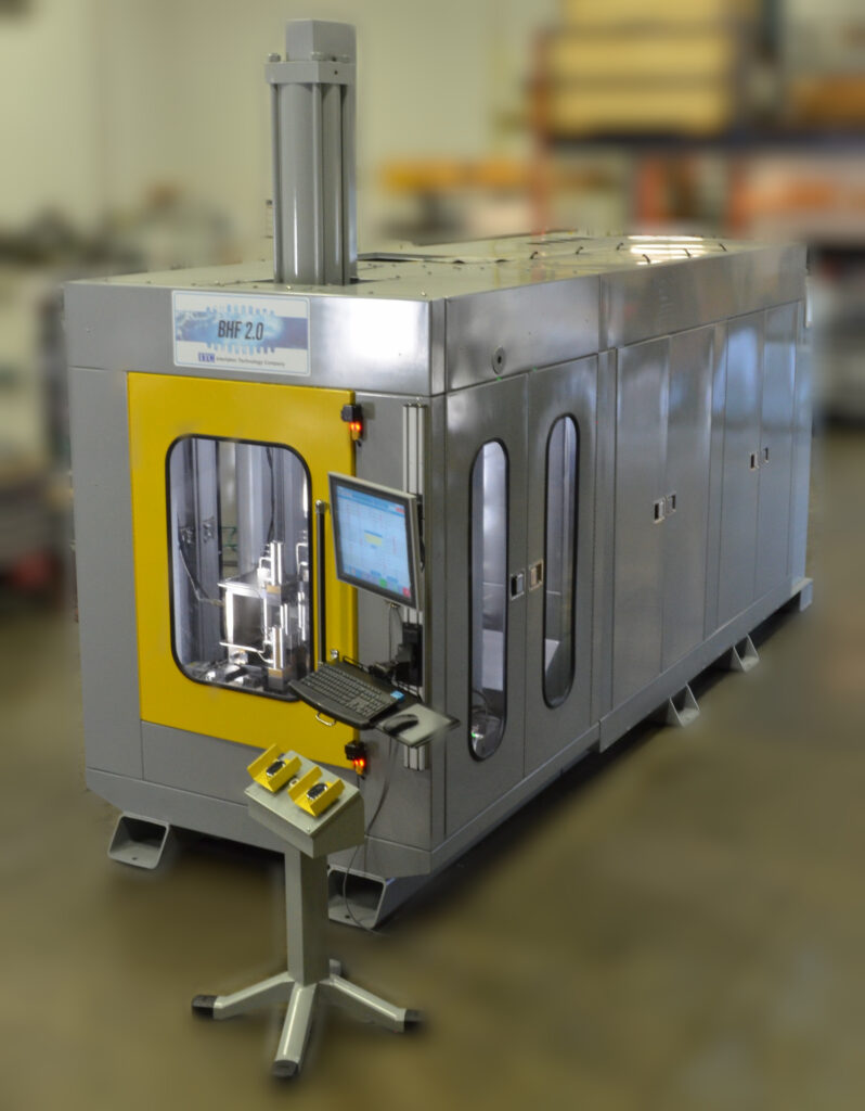
ITC designs a bellows forming system based on the size of the convolutes in your part. We define a small bellows as one with convolute diameter of 1/8″ to 1″. Medium is 1.5″ to 3.5″. Tooling is built based on the part requirements. The smaller the diameter the higher the pressure needed to form.
If necessary, ITC designs intensifiers up to 30,000 psi.
Tube
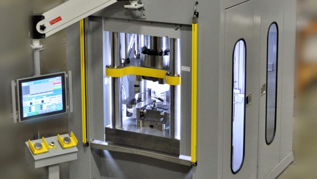
Hydroforming begins where traditional manufacturing processes end. Hydroform components simply perform better and allow for greater design flexibility. ITC helps you overcome quality issues, reduce cost, and lower component part counts. Our engineers determine the maximum forming pressure necessary and component material thinning. For many applications, hydroforming just makes sense. Tube hydroforming reduces weight and increases strength and stability. Interlaken specializes in smaller hydroforming presses: THF 0.5-THF 3.0 approximately 125 to 1000 tons. ITC presses use closed loop control of forces, motions, and pressures to produce high quality parts that cannot be manufactured by traditional processes. State-of-the-Art control software allows users to develop intricate recipes that can be both time and event dependent.
System size is determined by part geometry and the pressure necessary to form the part. The table below lists some general guidelines for a few key specifications.
Systems | THF 0.5 | THF 1.0 | THF 2.0 | THF 3.0 |
|---|---|---|---|---|
Clamping Force | 125 Tons 1112 kN | 250 Tons 2224 kN | 500 Tons 4448 kN | 1000 Tons 8896 kN |
Blank Part Diameter | < 1" < 25mm | 1" - 2" 25 - 50mm | 2" - 3" 50 - 75mm | 3" - 4" 75 - 100mm |
Blank Wall Thickness | < 0.02" < 0.5mm | 0.02" - 0.05" 0.5 - 1.25mm | 0.05" - 0.1" 1.25 - 2.5mm | 0.1" - 0.15" 2.5 - 3.75mm |
Max Forming Pressure | 90,000 psi 620 MPa | 30,000 psi 206 MPa | 30,000 psi 206 MPa | 30,000 psi 206 MPa |
Elevated Temperature
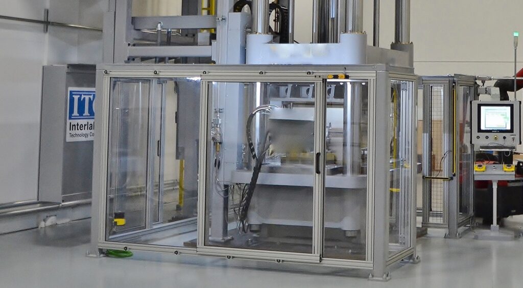
Interlaken has expertise in elevated temperature forming (ET) of aluminum tubes. Utilizing temperature to increase formability and decrease pressures and forces required compared to room temperature forming. Aluminum responds well to temperatures that enable up to 250% expansion from starting tube blank profiles. ET is a process that allows for optimizing the part profile to reduce part count in assemblies into single part form. This saves on material and tooling costs. Part features are formed with high accuracy and repeatability. In general, tooling costs can be lower due to the reduced forces and pressures required to form the part(s).
Material Formability
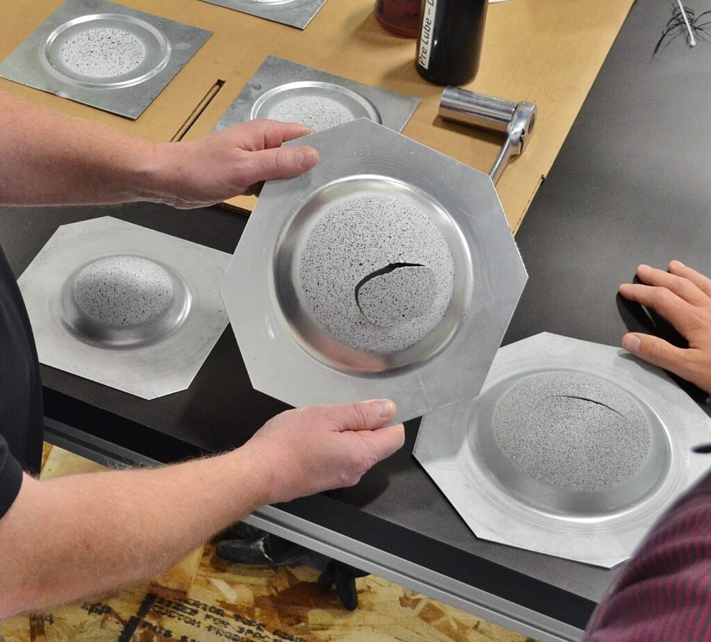
To form a complex geometry, the initial metal blank undergoes stretching, bending, a combination of the two, or drawing. Forming properties are dependent on the thermal and mechanical history of the material. Using standard and accepted methodology and tooling, ITC systems will help you to determine the ability of your material to deform to produce complex parts. Strain is measured up to failure to discover the forming limits. This will pinpoint bendability, stretchability, stretching at the edge, bending under stretching, and drawability.
Learn more:
- ServoPress
- Simulators
- Lubricant
ServoPress
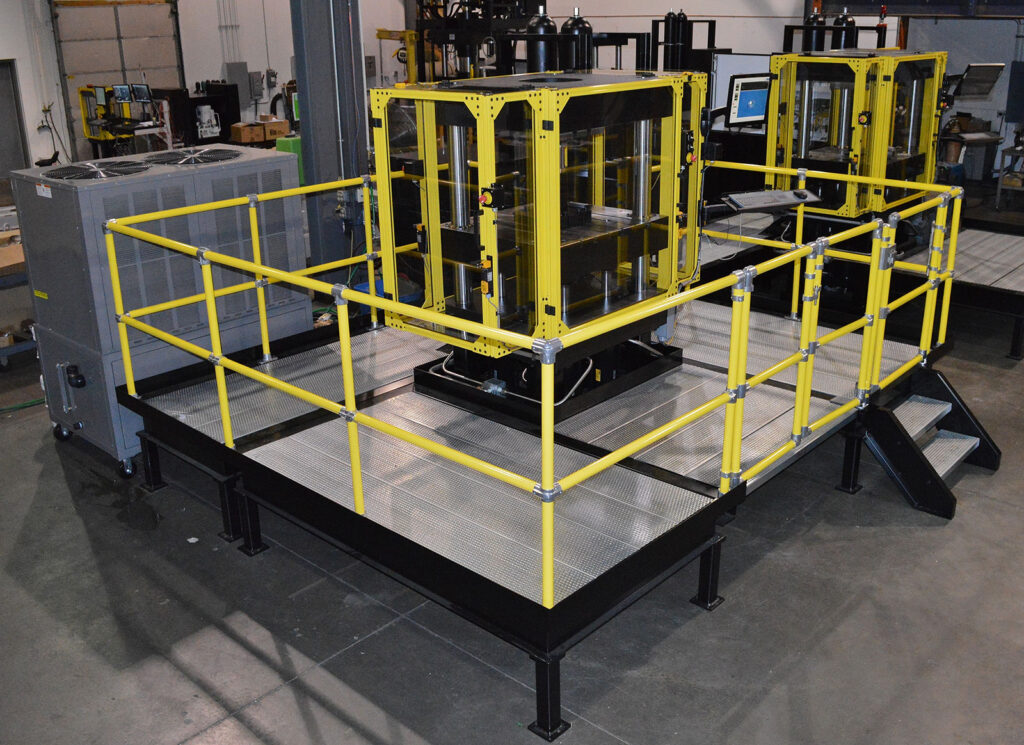
The ITC ServoPress line consists of double acting, servo-controlled hydraulic presses designed for laboratory and production use. The systems control, monitor, and record metal forming process parameters such as clamp force, clamp position, punch force, and punch position. They’re capable of simulating mechanical press speeds and velocity profiles. The versatility of the SP75, SP150, SP225, SP400, and SP600 makes them a great tool for enhancing your product development, production, and quality control processes.
The ServoPress allows you to:
- Quickly evaluate forming properties of sheet and tube for more accurate design models.
- Easily prototype parts without interrupting production presses.
- Optimize forming process variables and rank lubricants to improve part quality and press productivity.
- Check the quality of incoming materials to avoid production problems associated with variability in forming properties.
- Engage in tool development and process development.
- Evaluation of lubricants.
- Evaluation of properties at elevated temperature.
ServoPress Standard Tooling/Tests
Hydraulic Fluid Bulge
Interlaken Technology Hydraulic Fluid Bulge tooling consists of an upper and lower die set with cylindrical cavity, a piston to create pressure, pressure sensor, and a fluid catch tray with drain.
ITC Gas Bulge
The ITC Gas Bulge (typically used for elevated temperature testing) consists of a heated, upper and lower die set with an upper cylindrical cavity, 5-pin heater connections with thermocouples, gas line with pressure sensor, and water lines to cool each die.
Hole Expansion
The Hole Expansion tooling consists of a standard punch base with a conical tip attachment. A clamping ring set with 40mm diameter hole is standard. Varying diameters for the upper ring are available to accommodate various testing standards. Sample thickness can range from 1.2mm to 6.0mm. The conical punch is forced through a 10mm starting hole in the sample until a crack forms. The test is stopped manually based on this visual cue. The test is utilized to evaluate flange forming potential. Plastic Strain Ratio, Total Elongation, Quantity and Shape of inclusions all effect results.
Limiting Dome Height
Limiting Dome Height (LDH) tests using a two-inch or four-inch ball, are run with a rectangular blank. Nakajima tests use the same tooling, but a circular blank. The LDH test is a modified hemispherical dome test. Instead of a fully clamped blank, strips of varying widths are clamped on the ends by a lock bead and then deformed with a hemispherical punch (most commonly four inches in diameter). Changing the width of the sample allows the strain state to be matched to the strain state of the stamping under investigation. The samples are deformed until the sample fails. The ServoPress monitors the punch load throughout the test and the failure is depicted by a drop in punch load. The software records the dome height with respect to the maximum load recorded. This dome height is the Limiting Dome Height for the given sample width. Several sample widths are run to determine the width that yields the minimum dome height. This minimum dome height is known as the LDH0.
Marciniak Cup Test
The Marciniak Cup Test is a modified dome test. A four-inch diameter cylindrical punch is typically used with the standard Limiting Dome Height (LDH) clamp rings. The blank is fully clamped and a carrier blank is typically used. The carrier blank is made from the same size blank as the test blank, with a two-inch diameter hole punched in it. The carrier blank deforms more easily over the cylindrical punch and carries the test blank over the punch radius without the localization of strain in this area. This results in a more uniform strain distribution over the flat top of the formed test blank.
Limiting Draw Ratio
The Limiting Draw Ratio (LDR) test determines the deep drawability of the material. It uses a fixed punch geometry and circular samples of increasing diameters. Draw ratio = Blank diameter/Punch diameter. The larger the blank diameter that can be formed, the higher the LDR.
OSU Formability Test
The OSU Formability Test is used for both sheet metal formability and lubricant ranking. The die set provides an alternative to the LDH test. The OSU test utilizes a horizontal, cylindrical punch, which increases the area in plane strain. The forming operation is more controlled, and less sensitive to sample width, allowing for greater repeatability in results. The test provides quick and accurate correlation of metal and lubricant behavior during the forming process. A 0.50 inch diameter cylindrical punch (Forming 50 tool) and related clamping geometry is typically used for testing thin sheet (<0.062″ thick) and ductile materials. A 1.00 inch diameter cylindrical punch (Forming 100 tool) and related clamping geometry is typically used for thick sheet and more brittle materials. The sample size is typically 4.88 inches wide by 10 inches long. The width may be varied, but this reduces the area in plane strain, which increases scatter in results.
Simulator Test Systems:
Draw Bead Simulator
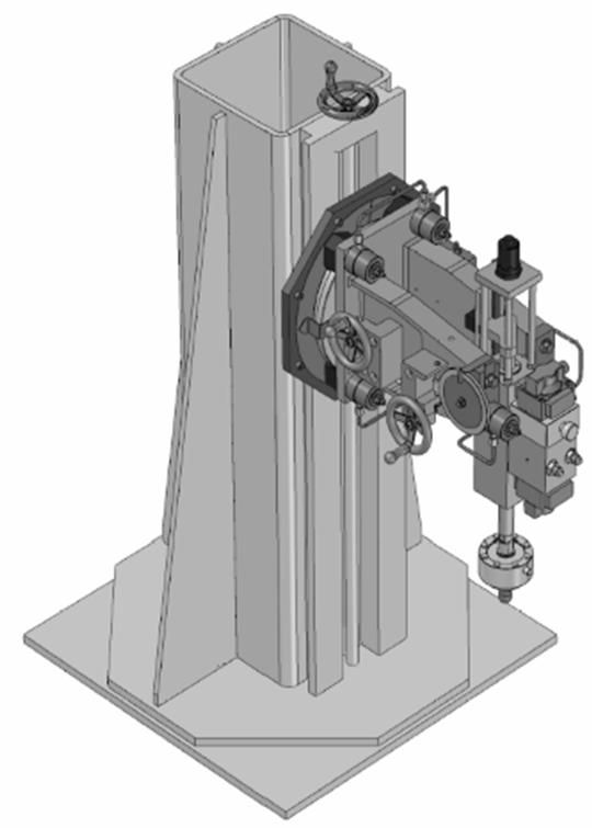
The Interlaken Draw Bead Simulator (DBS)is a two-axis hydraulic system for friction testing on sheet metals. There are two hydraulic actuators positioned at a 90-degree angle. The Bead actuator provides the draw bead loading, which forces the draw beads together either squeezing the sample or providing a prescribed clearance with a roller tool. The Draw actuator provides the draw force to pull the sheet metal specimen through the draw beads. The typical work is a clamping operation on one end of the specimen strip, while the Bead actuator forces the draw bead tooling together over the opposite end of the strip. The Draw actuator then pulls the specimen strip through the draw bead tooling one time. Rate and/or force of the actuators may be adjusted and data collected over the testing procedure.
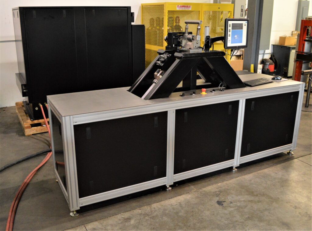
90 Degree Bend Test System
The 90 Degree Bend Test System is typically used for determining the coefficient of friction, lubricant ranking, and springback effects in the sheet metal forming process. The test involves drawing a test strip over a bead roller that is either fixed in rotation or controlled to roll at a desired rate. There are two linear actuators positioned 90 degrees from each other with the bead roller located at the intersection of the two actuators. The bead roller is held fixed or controlled to rotate at a defined rate by utilizing a rotary hydraulic torque motor. By using fixed and free rolling bead testing, the 90 Degree Bend Test provides an accurate coefficient of friction measurement. The sample size is typically 2.00 inches (50.8mm) wide by 24 inches (609.6mm) long.
ITC 600 Ton Forming Simulator
The intended use of the Interlaken 600 Ton Forming Simulator is for ductile sheet metal formability testing. The system is a computer controlled, double acting hydraulic press. The double actions are comprised of a moving clamp plate in the vertical axis and a punch actuator in a vertical axis. The clamp and punch axis both utilize downward acting cylinders that react against the bottom clamp plate. Both axes utilize force and position sensors and can be independently controlled using either force or position as feedback.
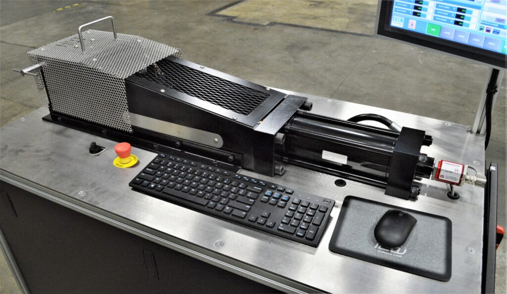
ITC Dent Test System
The Interlaken Technology Dent Test System provides the operator with the ability to evaluate the dent resistance of material specimens from something as simple as a 9″ “pie pan” type specimen to full body panels and even complete automobiles. This machine allows the operator to do static testing in completely automated fashion.
Lubricant
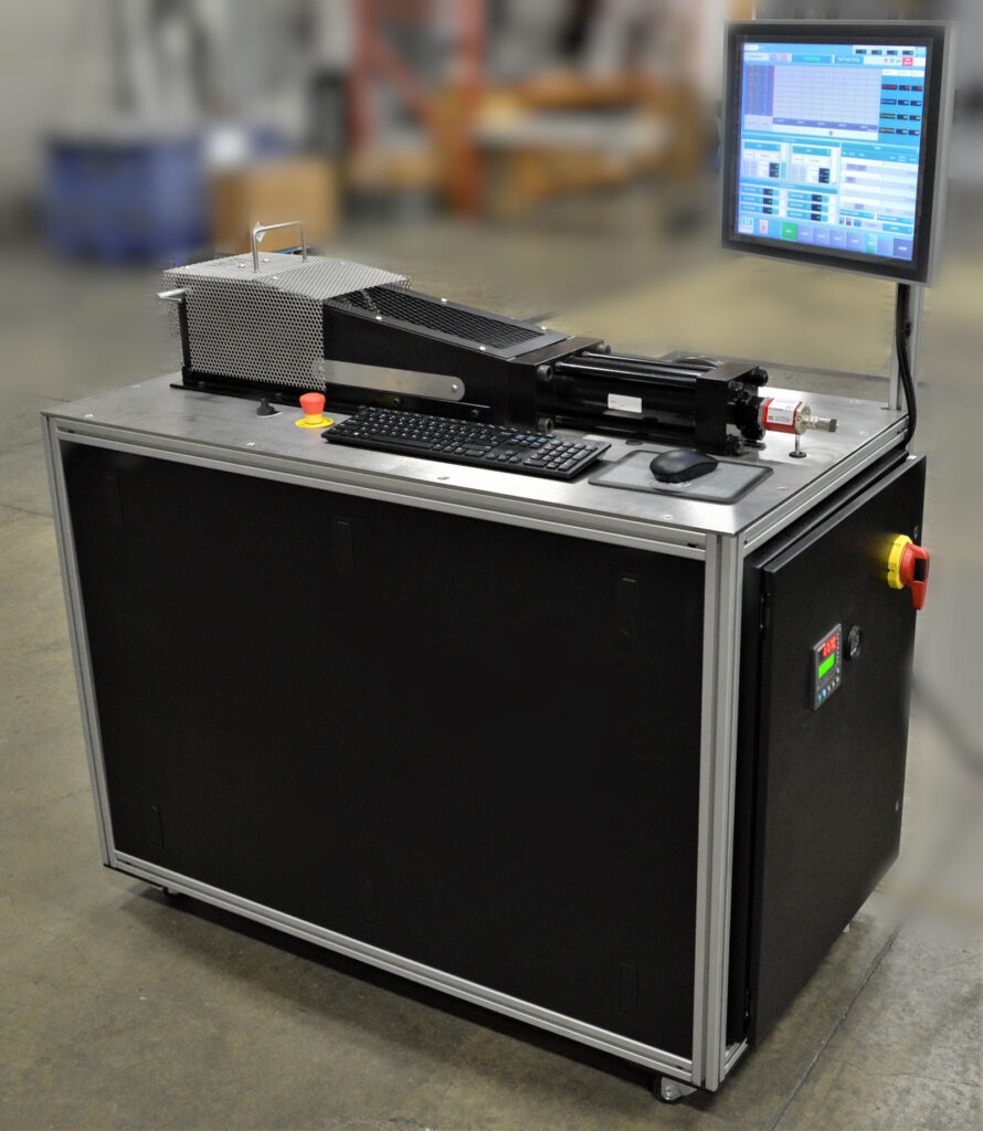
The versatility of the ITC Draw Bead Simulator and Servo Press SP75, makes them great tools for enhancing your product development, production, and quality control processes by allowing you to:
- Quickly evaluate lubricant properties on sheet metal for more accurate design models.
- Easily compare lubricants without interrupting production presses.
- Optimize forming process variables and rank lubricants to improve part quality and press productivity.
- Check the quality of incoming materials to avoid production problems associated with variability in forming properties.
Specialized
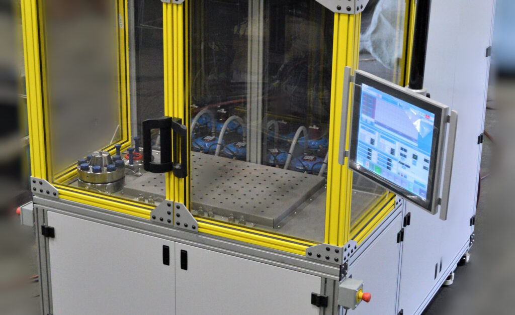
Combining its expertise in ultra-high pressure, controls, data acquisition, and high force hydraulics, Interlaken’s integrated package of pressure testing systems offer the dependability required for production coupled with the precision and repeatability necessary for R&D. Standard systems are available for pressures up to 100,000 psi (7000 bar). A network ready digital controller provides closed loop machine control and real-time data acquisition.
Learn more:
- Pressure/Leak/…
- Autofrettage
Pressure, Leak & Burst
Testing applications in markets using:
- Pipes
- Fittings
- Hoses
- Valves
- Vessels
- Chambers
- Brake Lines
- Steering Pumps
- Fuel System Components
- Iron Castings
- Weldments
- HVAC
- Automotive
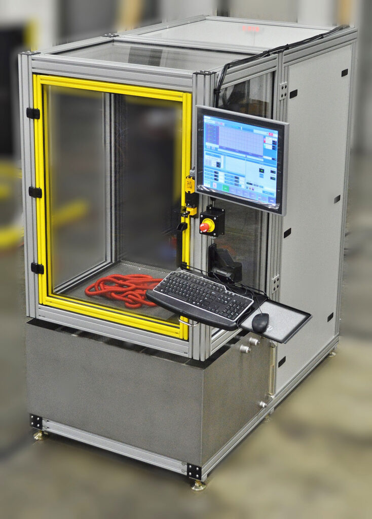
Pressure, Leak & Burst Systems include:
- Multi-pressure circuit capability
- Servo-controlled intensifier
- Hydraulic power supply
- Low pressure part filling and pressure intensifier charging
- High flow pump with indicator filter
- Reservoirs with low & high level switches
- Pressure and temperature sensor on the inlet side of the test piece
- Safety glass door with integrated safety locks
- Easy load/unload access
- Spacious testing area
- Single point pressure connection port
- Convenient access to mechanicals
- Ergonomic design
- Configurable HMI
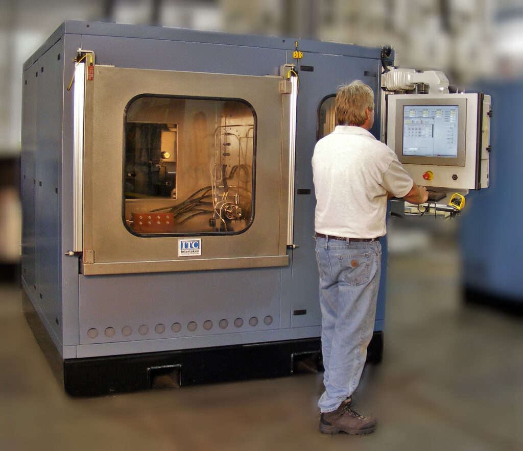
ITC equipment meets all OSHA requirements for operator safety. Interlaken is a UL508A panel shop. All electrical equipment is UL/ULC labeled.
Autofrettage
The Autofrettage technique is used on thick-walled metal tubes or components, to improve the durability of the part by creating a compressive residual stress at the bore. It dictates a pressure that is high enough to plastically deform the bore of the part, but not so high that it bursts the part. The pressure is applied to the inside of the tube. The result after the pressure is removed, is the elastic recovery of the outer wall puts the inner wall into compression, providing a residual compressive stress. The main reason to autofrettage a part is to increase its fatigue life. The applications are typically heavy walled tubes that experience cyclic loading and are thus prone to fatigue. Applications where this process is used include diesel engine components such as fuel rails and fuel lines, hydraulic cylinders, oil field components and waterjet components such as cylinders and check valves.